Linear Motor technology turns electrical energy into straight-line motion without converting rotation through gears, belts, or ball screws. It is often described as a rotary motor unrolled flat. The “rotor” becomes a moving slider, while the stator becomes a track containing coils or magnets. When controlled currents pass through the coils, electromagnetic force pushes the slider along the guideway. Motion can be rapid, precise, and remarkably clean.
Industry data shows why this technology matters. MarketsandMarkets’ Linear Motor Market report projects continued growth through 2028, driven by semiconductor equipment, electronics manufacturing, robotics, and automated inspection. Grand View Research also identifies industrial automation as a major demand area, although published forecasts differ because market definitions are not consistent. Some reports include voice-coil actuators, while others focus only on permanent-magnet linear motors. That distinction matters.
The basic principle is simple. The engineering is not.
A linear motor must manage force, heat, vibration, acceleration, and position feedback at the same time. In a factory, a magnetic track may move a wafer stage by micrometres, or carry a cutting tool across a long production line. Encoders continuously report position, allowing the drive system to correct small errors. Compared with mechanical transmission systems, linear motors can reduce backlash and maintenance. However, they may require expensive magnets, careful thermal design, and advanced motion control. This article explains what a Linear Motor is, how electromagnetic force creates movement, and where its practical advantages and limitations appear in modern machines. Forecasts are useful, but real performance still depends on application, installation, and engineering judgment.
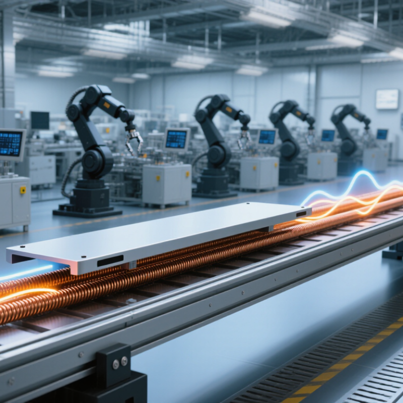
What Is a Linear Motor?
A linear motor is an electric machine that creates straight-line motion directly.
Unlike a rotary motor, it does not need a shaft, gearbox, or crank to convert rotation. Its active parts are often called the forcer and the track. One part produces a changing magnetic field. The other carries magnets or conductors that respond to it. This interaction generates thrust along a defined path. In simple terms, it is a rotary motor opened and laid flat. That description helps, although real designs are more complex.
When alternating current enters the motor coils, the magnetic field shifts in sequence.
The forcer is pulled or pushed along the track. A controller adjusts current, position, and speed many times per second. Sensors can report the moving part’s location with fine resolution. This enables precise movement in inspection equipment, automated slides, laboratory systems, and transport mechanisms. A properly aligned guide is essential. The motor supplies force, but bearings or rails usually manage the load and direction. It cannot correct every mechanical problem.
Linear motors may use permanent magnets, iron cores, or air-core structures.
Each choice affects force, heat, weight, noise, and cost. Air-core designs often reduce cogging, while iron-core designs can provide stronger force in a smaller area. Engineers must also consider cooling and cable movement. Heat buildup can reduce accuracy and shorten component life. In practice, performance depends on the complete machine, not the motor alone. A faster motor is not always the better choice.
How a Linear Motor Produces Direct Motion
What Is a Linear Motor and How Does It Work?
A linear motor produces direct motion instead of rotary motion. Its moving part travels along a straight path, like a train sliding along a rail. The motor uses magnetic fields to create thrust. One section contains coils, while another carries permanent magnets or conductive material. When controlled current enters the coils, changing magnetic fields pull or push the moving section forward.
The process resembles cutting open a conventional motor and laying it flat. There is no crank, gearbox, or screw converting rotation into travel. This direct design can improve speed, positioning accuracy, and mechanical efficiency. Sensors usually report the mover’s position to a controller. The controller then adjusts current within milliseconds. Small alignment errors can still cause vibration, heat, or uneven force. The idea sounds simple. Real systems are not.
Tips: Match the motor’s force rating with the actual load, acceleration, and friction. Keep the guide surface clean and rigid. Check feedback sensors regularly, because poor position data can create sudden errors. A useful test is to compare commanded travel with measured travel at several speeds. This may reveal problems that a slow bench test misses. In my view, designers sometimes focus too heavily on peak speed. Smooth, repeatable motion often matters more in daily operation.
Key Components and Operating Principles
What Is a Linear Motor and How Does It Work?
Key Components and Operating Principles
A linear motor creates straight-line motion instead of rotating motion. Its main parts are the stator, moving assembly, coils, magnets, position sensor, and electronic controller. The stator provides the active magnetic track. The moving assembly, often called the translator, carries either permanent magnets or energized coils. Guide rails support the load and maintain a narrow working gap.
The operating principle depends on magnetic force. When controlled current flows through the coils, it produces a changing magnetic field. This field interacts with the permanent magnets and pushes the translator along the track. Reversing the current sequence reverses the direction. Increasing current usually increases thrust, although heat and electrical limits restrict that relationship. The controller switches current at carefully timed intervals. An encoder reports position and speed, allowing feedback corrections during movement.
During bench testing, even a small rail misalignment can create vibration, noise, and uneven force. It is easy to blame the controller first. That assumption is often wrong. Cable resistance, bearing friction, sensor resolution, and poor thermal contact can also reduce accuracy. A useful setup checks mechanical alignment before changing software settings. Linear motors can move quickly and precisely, but their performance depends on the complete system. The motor, guide structure, feedback device, and controller must work as one unit. My own simplified explanations sometimes overlook friction, which deserves closer measurement in real installations.
Main Types of Linear Motors
What Is a Linear Motor and How Does It Work?
A linear motor creates straight-line motion without converting rotary motion through screws, belts, or gears. Its moving part, called the forcer, travels along a magnetic track. Coils receive controlled electrical current, producing a changing magnetic field. This field pushes or pulls permanent magnets. The result is direct thrust, accurate positioning, and rapid acceleration. It moves directly. However, heat, alignment, and control settings strongly affect performance.
Flat linear motors are common in inspection equipment, semiconductor tools, and precision stages. Their wide magnetic tracks provide useful force and simple mounting. U-channel motors place magnets inside a channel, while the forcer moves between them. This design can protect the magnetic path and reduce sideways forces. Tubular linear motors use a cylindrical structure. They suit compact actuators, laboratory devices, and applications needing enclosed motion. Space matters here.
Iron-core motors produce high force because their magnetic field concentrates through iron teeth. They often support heavier loads, but they may create cogging, vibration, and audible noise. Ironless motors provide smoother motion and lower moving mass. They are valuable for delicate scanning and positioning tasks, though their force density can be lower. Voice-coil motors are another type. They offer short, smooth strokes and simple control, but they usually cannot hold position without continuous current. The categories overlap. Choosing a motor requires checking stroke length, load, speed, accuracy, cooling, and duty cycle. A technically elegant choice can still fail when the installation environment is underestimated.
Applications, Benefits, and Limitations
What Is a Linear Motor and How Does It Work?
A linear motor creates direct motion along a straight path instead of rotating a shaft. It uses magnetic fields to push or pull a moving part across a stationary track. In practical systems, sensors and controllers adjust current, position, and speed continuously. This design can deliver smooth movement, accurate positioning, and rapid acceleration. It also removes several mechanical transmission parts, such as belts, gears, and screws.
Applications include semiconductor equipment, laboratory automation, packaging machines, and high-speed transport systems. Engineers often choose linear motors when precision matters more than low initial cost. With fewer contact surfaces, maintenance may decrease. Motion can also feel remarkably clean and quiet. Still, performance depends on installation quality. Heat, dust, vibration, and poor alignment can reduce accuracy. The system may require advanced control software and careful thermal management. These requirements add complexity, and sometimes the expected savings never appear.
Tips: Define the required travel distance, load, speed, and accuracy before selecting a motor. Measure heat buildup during realistic operating cycles, not only short demonstrations. Protect the track from contamination. Leave space for inspection and cable movement. A linear motor is not automatically better; for simple, slow motion, a conventional mechanism may remain more practical. My own design reviews often reveal this uncomfortable detail: impressive acceleration can hide unnecessary energy use. Testing the complete machine, including payload changes, gives more reliable results than judging the motor alone.
What Is a Linear Motor and How Does It Work?
This chart shows representative operating-speed ranges for common linear-motor applications. A linear motor produces motion directly along a straight path, eliminating the need for mechanical rotary-to-linear transmission components such as screws, belts, or gears. Actual performance depends on motor design, payload, stroke length, cooling, and control system.
FAQS
A linear motor creates straight-line motion directly. It does not need a shaft, gearbox, crank, or screw. Its moving part travels along a track. Think of a rotary motor opened and laid flat.
Controlled current enters coils and creates changing magnetic fields. These fields push or pull magnets along the track. A controller adjusts current, speed, and position repeatedly. The principle is simple. The system is not.
The main parts are the forcer, magnetic track, controller, sensors, and guide system. The motor creates thrust. Rails or bearings manage direction and load. It cannot repair poor mechanical alignment.
Common types include flat, U-channel, tubular, iron-core, ironless, and voice-coil designs. Flat models suit precision stages and inspection equipment. Tubular models fit compact actuators. Voice-coil models usually provide short, smooth strokes.
Iron-core motors usually produce stronger force in a smaller area. They may create cogging, vibration, and audible noise. Ironless motors provide smoother motion and lower moving mass. Their force density can be lower.
Usually, yes. The motor supplies forward thrust, but guides control movement and support the load. A dirty or flexible rail can cause vibration. Magnetic force does not guarantee accurate travel.
Heat buildup can reduce accuracy and shorten component life. It may also change performance during long operating cycles. Cooling, cable movement, and duty cycle deserve attention. Peak speed is not everything.
Match the force rating with load, acceleration, friction, stroke, speed, accuracy, and duty cycle. Check the available space and cooling method. A faster motor may perform worse in daily operation. That choice deserves a second look.
Compare commanded travel with measured travel at several speeds. Check feedback sensors regularly. A slow bench test may hide errors. Real movement can reveal them.
Conclusion
A Linear Motor is an electric machine that creates straight-line motion directly, eliminating the need to convert rotary motion into linear movement through gears, screws, or belts. It works by developing a controlled electromagnetic force between stationary and moving parts. When electric current passes through the motor’s coils, it produces a magnetic field that interacts with permanent magnets or another magnetic field, pushing the moving element along a track. By adjusting the timing, direction, and strength of the current, the system can achieve accurate speed and position control.
The main components of a Linear Motor include the stator, mover, coils, magnets, sensors, and control system. Common types include tubular, flat, iron-core, and ironless designs, each suited to different performance needs. Linear motors are used in automation, transportation, manufacturing equipment, robotics, and precision positioning systems. Their key benefits include fast response, high accuracy, smooth motion, and reduced mechanical wear. However, they may require sophisticated control electronics, careful heat management, and higher initial investment than traditional mechanical drive systems.
